A workable EPS production line layout follows the material in one direction: raw-bead receipt → pre-expansion → bead aging → molding → block conditioning or part cooling → cutting or finishing → packing → dispatch. The seven mistakes below create crossed forklift routes, unstable utilities, inaccessible machines, pentane accumulation, damaged beads and expensive rebuilding. Correct them on a scaled drawing before the foundation, pipe trenches and cable trays are fixed.
Machine footprints alone do not make a plant layout. The drawing must also reserve operating aisles, door and platen travel, mold or wire changes, maintenance withdrawal, overhead conveying, exhaust, drains, utility headers, work-in-process and a route for removing the largest component. A compact arrangement can be excellent; an arrangement that merely packs rectangles tightly is not.
The installation rule
Freeze the process flow first, then place equipment, then route utilities, and only then finalize the building interfaces. If the building drawing is frozen before the production sequence and maintenance envelopes, every later correction becomes civil work.
EPS Production Line Layout Review in One Table
| Review layer | What the drawing must show | Approval question |
|---|---|---|
| Material flow | Raw beads, expanded beads, molded products, scrap and finished goods | Does any normal route double back or cross a conflicting route? |
| People and vehicles | Operator stations, pedestrian aisles, forklifts, loading doors and exits | Can people reach an exit without walking through a machine or forklift envelope? |
| Utilities | Steam, condensate, cooling water, compressed air, vacuum, power, exhaust and drains | Are peak users close enough to the headers, with isolation and service access? |
| Maintenance | Door swing, platen travel, mold handling, motor/pump withdrawal and lifting points | Can the largest service job happen without moving another production machine? |
| Future state | Reserved bay, capped headers, spare electrical capacity and extension route | Can the planned next machine be added without stopping or rebuilding the whole line? |

Mistake 1: Drawing a Straight Line That the Material Cannot Follow
The correct flow is one-way, but it is not necessarily one geometric straight line. Raw bead bags or bulk containers need a receiving and quarantine position near the pre-expander. Light expanded beads then move through large pneumatic pipes to aging silos. Molded blocks or parts are bulky, so their route to conditioning, cutting and packing needs much more physical volume than the incoming material route.
A common bad layout puts the pre-expander, molder and cutter in a neat row while ignoring where silos, work-in-process and packing actually sit. Operators then return material across the same aisle, forklifts pass the molding station, or finished boards travel back toward raw-material receiving. The result is extra handling and a collision risk that grows with output.
Fix: draw five separate lines on the plan: raw material, expanded beads, saleable product, scrap/regrind and people/forklifts. Give each line a direction and a transfer method. Crossings must be deliberate, visible and controlled. For an insulation-board line, place pre-expansion and silos upstream of the block molder, then reserve conditioning space before the cutting and packing cell. For molded packaging, route the silos toward the shape-molding bank and keep finished-part packing on its dispatch side.
Mistake 2: Treating Aging Silos as Empty Floor Space
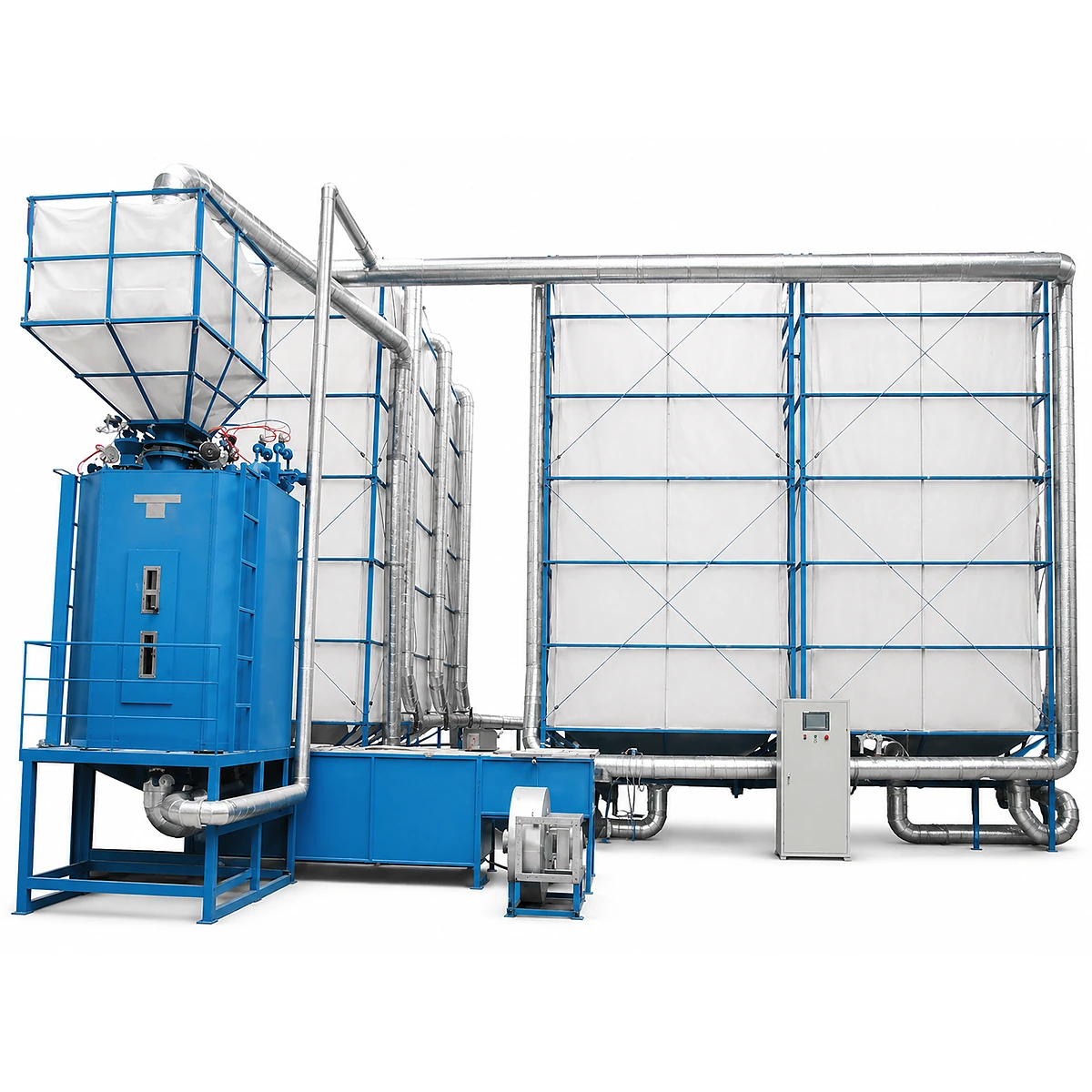
Silos are a volume, height and ventilation decision, not just circles on a floor plan. The layout needs the silo frames, top-fill lines, bottom discharge, inspection gaps, valves, level devices and access for replacing fabric or panels. Silo capacity must follow pre-expander output, required aging time, grade separation and production buffer; otherwise the factory either starves the molders or discharges beads before they are ready.
Putting silos in whatever corner remains can create long conveying routes with too many bends, low ceilings above the fill points and no safe maintenance approach. It can also put the highest pentane-release area beside an ignition source or an occupied room. The EPS aging-silo sizing guide explains the capacity calculation and batch separation logic.
Fix: approve a silo elevation as well as a plan view. Show clear building height, top piping, discharge level, frame foundations, access gaps and the exhaust concept. Put the silo bank between pre-expansion and molding so the pneumatic path is short and the production sequence stays legible. Do not reduce the required aging buffer merely to make the drawing fit.


Mistake 3: Adding Steam, Vacuum and Drains After the Machines Are Placed
Utility routing can make a good machine layout perform badly. EPS pre-expanders and molding machines require stable steam at the specified point of use. Long undersized headers, poorly drained low points and unplanned simultaneous demand create pressure drop and wet steam. Vacuum and cooling systems lose performance when pipe length, diameter, bends, elevation and recovery time are ignored. Condensate and floor drains need gravity, separation and accessible cleanouts.
A boiler nameplate does not correct a restrictive distribution system. The EPS boiler sizing guide separates connected load from peak simultaneous demand; that calculation and the layout must be reviewed together. Staggering molding cycles may reduce peaks, but the control plan is not a substitute for adequate headers.
Fix: create a utility matrix for every machine before foundations are released. Record connection size, pressure or vacuum requirement, peak and average demand, drain point, isolation valve and maintenance access. Place the boiler/steam interface, vacuum pumps, cooling equipment and air compressor according to pipe performance, ventilation, noise, local code and service access. Show header sizes and tie-in points on the issued-for-installation drawing, not only on a later contractor sketch.
Mistake 4: Reserving Operating Clearance but No Maintenance Envelope
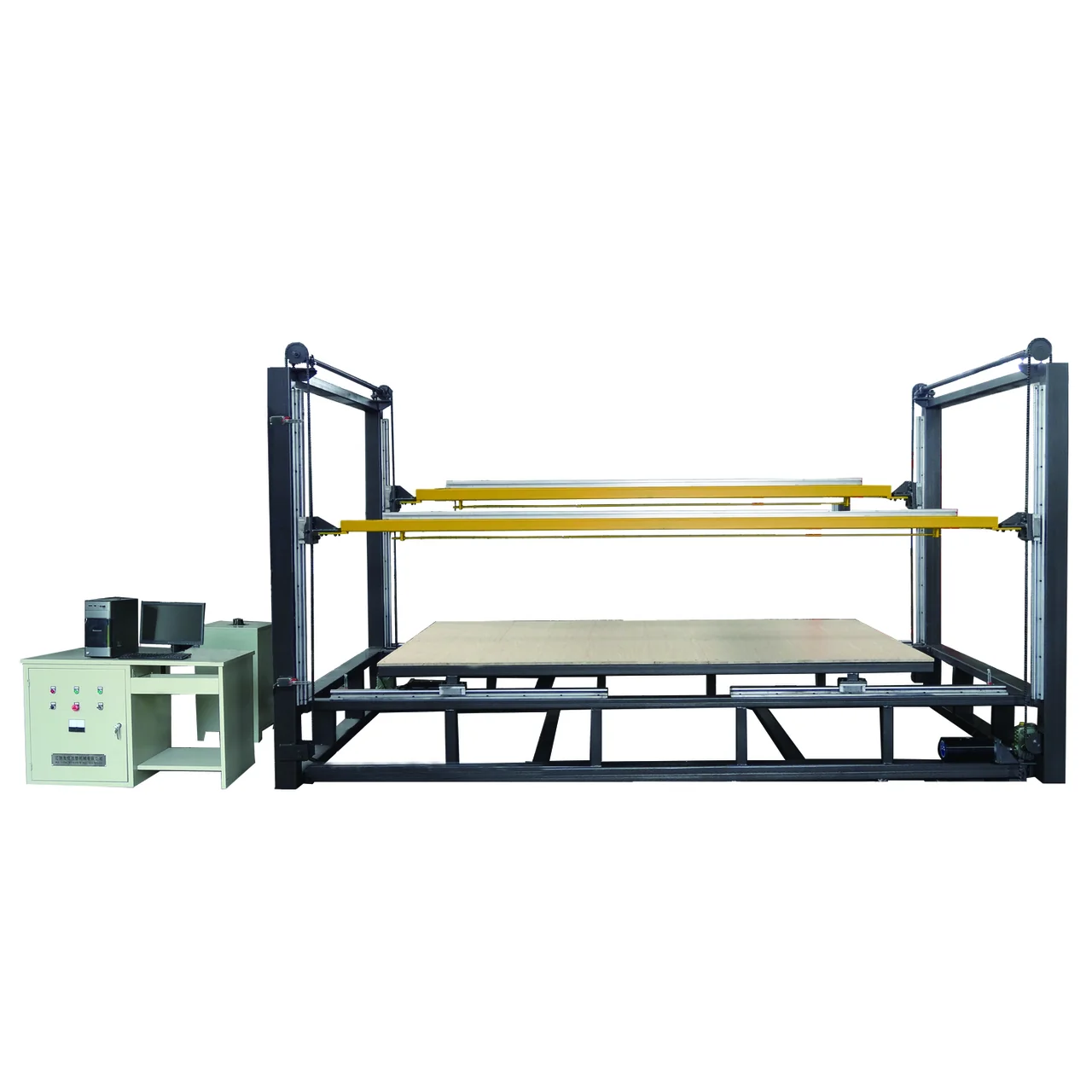
The aisle that lets an operator run a machine may be too small to repair it. Block-molder doors and platens travel. Shape molds need lifting and staging. Cutting lines need wire-frame access. Pumps, motors, heat exchangers and hydraulic components may have to be withdrawn in one direction. A wall, column or cable tray inside that path turns routine maintenance into demolition.
Fix: ask the supplier for a general-arrangement drawing that distinguishes the static footprint, moving envelope, operator zone and maintenance-removal envelope. Add the handling method: forklift, pallet truck, mobile crane or overhead beam. Verify the floor load and anchor pattern at the same revision. Finally, trace how the largest replaceable component leaves the building. If another installed machine must be disconnected first, the layout is not maintainable.
Mistake 5: Mixing Pentane, Ignition Sources and Escape Routes
EPS raw beads and recently expanded beads release pentane, a flammable vapor. NIOSH lists n-pentane with a 1.5% lower explosive limit, so ventilation, release points, gas detection and ignition-source control must be engineered for the actual plant. Local fire, electrical and building rules determine the final hazardous-area classification; a machinery supplier's concept drawing cannot replace that assessment.
Safety also changes the physical layout. The U.S. OSHA machine-guarding rule requires protection from points of operation and moving parts. Its exit-route design requirements require unobstructed, adequately arranged routes. The NIOSH Pocket Guide for n-pentane provides exposure and flammability data. These references are useful baselines; the authority having jurisdiction approves the project.
Fix: mark release zones, exhaust pickup points, electrical classifications, hot work, boiler or burner locations, charging areas, exits and assembly points on one coordinated safety plan. Keep escape routes independent from stored blocks, pallets and mold-change staging. Review normal operation, startup, shutdown, spill/release, fire and power-loss states before installation.
Mistake 6: Forgetting Packing, Scrap and Truck Movement
The machine is not the end of the line. EPS products occupy large volume relative to weight. Finished blocks need conditioning and cutting queues; boards need stacking and wrapping; molded packaging needs inspection, nesting or bagging. Offcuts need a controlled route to crushing, dedusting and mixing without contaminating finished-product space.
A line can reach its machine-cycle target and still miss shipments because packing blocks the cutter or the forklift must cross the operator aisle. Outdoor truck turning, dock height, weather protection and container loading also affect the last indoor bay.
Fix: calculate buffer positions from production rhythm and dispatch pattern. Mark one normal location for every pallet, mold, block waiting to cut, packed bundle and scrap bin. Separate inbound raw material from outbound finished goods where possible. Test the drawing with the largest forklift and vehicle swept path, including turning and reversing, not just vehicle width.
Mistake 7: Freezing Today’s Capacity Into Concrete
Future expansion needs physical and utility interfaces, not a note saying “phase two.” The reserved bay is useless if a column blocks the platen, the steam header ends on the wrong side, the electrical room has no spare feeder, or the next machine closes the only exit. Likewise, oversizing every system on day one can waste capital and reduce operating efficiency.
Fix: define the most likely next constraint: another molding machine, more silo volume, a second cutter, additional packing or a recycling cell. Reserve the exact bay and installation route, then provide capped utility takeoffs, electrical allowance, control-network access and drainage where justified. State which items are installed now and which are only provisioned. The EPS board production-line configuration is a useful starting point for mapping the equipment chain, but the expansion interface must match the buyer's product mix and building.
A Four-Pass Layout Approval Method
- Process pass: confirm products, densities, daily output, shifts, batch aging, machine cycle assumptions and every material route.
- Envelope pass: overlay static equipment, moving parts, operation, maintenance, lifting, WIP, forklifts and component-removal routes.
- Utility and safety pass: route steam, condensate, cooling water, vacuum, air, power, exhaust and drains; then review hazardous zones, guarding and exits.
- Installation pass: freeze foundations, anchors, trenches, openings, delivery sequence, lifting plan, datum lines and responsibility for every interface.
| Document to freeze | Minimum content | Who confirms it |
|---|---|---|
| Process flow diagram | Material states, capacities, buffers and scrap return | Buyer production lead + line supplier |
| General arrangement | Footprints, elevations, moving and service envelopes | Machine supplier + buyer project engineer |
| Utility schedule | Connection, quality, peak demand, isolation and drain | Machine supplier + local utility engineer |
| Safety/zoning plan | Release points, ventilation, ignition control, guarding and exits | Local qualified safety/fire/electrical professionals |
| Foundation and interface drawing | Loads, anchors, trenches, openings, datums and tolerances | Local civil engineer + installer + supplier |
What to Send Before Requesting an EPS Layout
The layout brief is also part of a complete RFQ. Use the EPS machine quotation preparation checklist to combine the building drawing with product, output, material, utility, automation and commercial requirements.
- Dimensioned building plan with columns, clear height, doors, docks, exits and floor-load information.
- Target products, dimensions, densities, daily output, shifts and expected product mix.
- Machine list, preferred automation level and any equipment that already exists.
- Local steam source, power voltage/frequency, water conditions, drainage and fuel availability.
- Raw-material delivery method, finished-goods packing format, truck/container access and forklift type.
- Local fire, environmental, electrical, pressure-equipment and permitting requirements.
- Planned expansion stage and the date or demand trigger that would activate it.
Layout CTA: send ChinaEps a dimensioned building drawing, target product list, daily output, utility conditions and planned expansion. Our production-line team can return a marked-up process flow, preliminary equipment arrangement and interface checklist for review with your local civil, utility and safety engineers. Request an EPS factory layout review →
Frequently Asked Questions
What is the best layout for an EPS production line?
The best layout keeps raw beads, expanded beads, molding, conditioning, cutting or finishing, packing and dispatch in a clear one-way sequence. It also separates people and vehicle routes, keeps steam and vacuum users near correctly sized headers, and preserves maintenance and expansion envelopes.
Should EPS aging silos be next to the pre-expander or the molding machine?
Place the silo bank between them. The exact position balances the pre-expander discharge route, silo top-fill height, required aging volume, ventilation and the feed route to the molders. Approve both the floor plan and the elevation before fixing the location.
Can the boiler and compressor be placed anywhere outside the workshop?
No. Their location affects pipe length, pressure loss, condensate drainage, intake/exhaust, noise, service access and local separation rules. A qualified local engineer should coordinate the equipment supplier's demand data with the building and applicable codes.
How much maintenance clearance should an EPS machine have?
There is no safe universal number. Use the model-specific general-arrangement drawing and reserve the full travel or withdrawal distance for doors, platens, molds, wire frames, motors and pumps, plus the selected lifting and transport method.
Why must the EPS layout account for pentane?
Raw and recently expanded EPS beads can release flammable pentane vapor. The layout therefore affects ventilation, gas detection, electrical zoning, ignition-source separation and emergency routes. Final requirements must be set by local qualified professionals and the authority having jurisdiction.
When should the final factory layout be frozen?
Freeze it only after the process, machine envelopes, utility schedule, safety zoning, logistics and future interfaces have been reviewed together. Foundations, trenches and cable routes should use the same approved revision and datum system.
The Decision Before Installation
A good EPS layout is not the drawing with the shortest distances; it is the drawing in which material, people, utilities, maintenance and future capacity can all move without conflict. Resolve those conflicts on paper. Moving a symbol costs minutes; moving a steam trench, silo frame or production machine after installation costs downtime and money.